
The hysteresis model does not included creep, but it is possible to add springs and dashpots to the backlash elements which will capture the creep behavior. The hysteresis model described here overcomes these difficulties by using backlash basis functions which are relatively easy to fit to experimental data and are numerically efficient to simulate. Of those that do describe this important detail,, the treatment of piezoelectric hysteresis in the model is often problematic in that either friction elements, such as the Maxwell resistive capacitor (MRC) are used, which are difficult to simulate, or nonlinear differential equations are used which have very heuristic fitting functions. Many models for PZT stacks have been developed in the literature, such as those in, but few incorporate the transfer of energy into a structure and out of the structure back into the device. The model described in this chapter is intended to be used as a necessary precursor for control design and simulation. These impacts necessitate high fidelity modeling of the PZT behavior, which can be quite rich and faceted.

In a linear sense, the hysteresis has an effect on the both the loop gain and phase margin. This will linearize the device to the accuracy of the sensor, and address creep, but the hysteresis nonlinearity has an impact on the loop stability which must be analyzed. This has led many to employ servo control with displacement sensing of the PZT elongation. To overcome these problems, it is possible to invert the hysteresis nonlinearity but this can only improve accuracy by one order of magnitude and leaves the creep issue unresolved. These two issues make open loop operation of these devices problematic since multiple displacements are possible for the same input and due to the fact that creep dissipates at very slow rates.
#Dynamic response of stack piezo actuators full
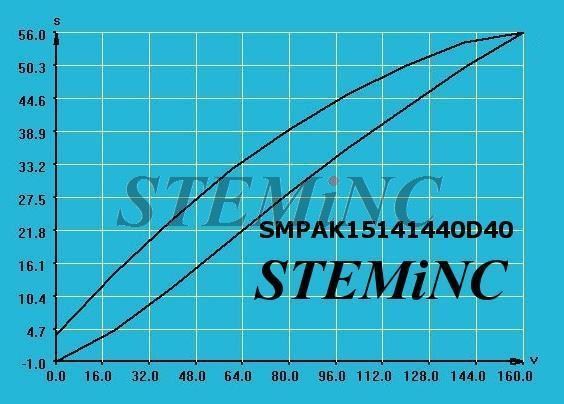
In addition, PZTs suffer from significant amounts of hysteresis (15 percent of full stroke) and creep which causes drift of the device over time. The first is that the stroke of these devices is limited to about 40 μm, which for some applications, necessitates the use of dual stage actuation or inchworm actuators which combine brake PZTs with actuation PZTs to extend the dynamic range of these devices. Three main issues, however, compromise the utility of these devices. Due to the piezoelectric effect, it can also be used as a sensor of force or displacement or for energy harvesting since current is produced by the device in response to an applied strain. It is used in various applications as an actuator including micromanipulation and ultrasonics. Due to its physical strength, chemical inertness, tailorability and low manufacturing costs, it is one of the most commonly used piezo ceramics. Lead zirconium titanate (PZT) was first developed around 1952 at the Tokyo Institute of Technology. Taken together, the actuator and sensor model can be used for the development of piezo actuated control algorithms. Sensors of this type are often used with feedback control to linearize the behavior of the device. In addition, a simplified model of a modulated full bridge strain gauge is derived based on test data which includes the effect of intrinsic bridge imbalance.
#Dynamic response of stack piezo actuators free
Data from laboratory experiments using a load frame and free response tests is used to estimate the PZT model parameters. The piezo model can also be used to predict the current usage of the PZT which depends on the slew rate of the voltage applied to the PZT. Modeling of the piezo stack capacitive hysteresis is achieved using backlash basis functions. This model allows for easy integration of the piezo stack with a structural finite element model (FEM) and includes the flow of energy into and out of the piezo element, which is governed by the transducer constant of the piezo element.

In this chapter a full electromechanical model of piezoceramic actuators is presented.


 0 kommentar(er)
